
From $. Please contact us for specific project
Download Data Sheet here
Product Overview
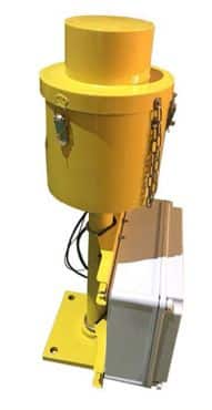
The SAGA (Azimuth Guidance System for Approach) represents an advanced visual alignment solution engineered specifically for challenging heliport operations. This sophisticated dual-unit flashing light system delivers unparalleled approach guidance accuracy, enabling pilots to maintain precise azimuth alignment during critical landing sequences. Designed for installations where terrain constraints, urban obstacles, or traffic control requirements demand specific approach vectors, the SAGA system transforms complex heliport approaches into confident, controlled operations through synchronized visual cueing technology.
Engineered by PLUSAFE Aviation Lighting, this comprehensive guidance system combines threshold identification with approach azimuth guidance, creating a unified visual reference that significantly enhances operational safety in crowded urban environments, remote facilities, and restricted approach corridors.
Key Features
• Dual-Unit Synchronized Architecture – Master and slave configuration delivers coordinated flashing sequences that provide instantaneous visual feedback regarding aircraft position relative to the optimal approach path
• Extended Visual Acquisition Range – Achieves 10 nautical mile visibility under standard atmospheric conditions, ensuring early approach alignment and enhanced situational awareness for incoming aircraft
• Precision Angular Coverage – Maintains ±15° coverage sectors on both sides of the designated approach axis with exceptional azimuth accuracy of ±0.45°, supporting consistent alignment guidance
• Intelligent Flash Sequencing – Variable delay timing (60-300ms) between unit flashes creates directional cueing that intuitively guides pilots toward the centerline approach path
• Robust Environmental Protection – IP65-rated enclosures withstand harsh weather conditions while maintaining reliable operation across extreme temperature ranges from -40°C to +50°C
• Energy-Efficient Operation – Total system power consumption below 250 watts minimizes operational costs while maintaining superior light output through pre-focused 105W reflector lamp technology
• Frangible Construction Elements – Breakaway leg assemblies minimize damage risks during accidental contact while maintaining structural integrity under normal operating conditions
Certifications and Compliance
• ICAO Annex 14, Volume II – Fully compliant with 4th Edition (July 2013) international standards for heliport visual aids and approach guidance systems
• French STAC Certification – Meets stringent European technical aviation requirements for heliport lighting installations
• IP65 Environmental Rating – Certified protection against dust ingress and water jets from any direction
• Electrical Safety Standards – Compatible with global power infrastructure supporting 110-230VAC, 50/60Hz operation
Technical Specifications
Optical Performance:
-
Visual Range: 10 nautical miles (standard visibility)
-
Angular Coverage: 30° total sector (±15° from approach axis)
-
Azimuth Accuracy: ±0.45°
-
Flash Frequency: 0.5 Hz
-
Inter-flash Delay: 60-300 milliseconds (position-dependent)
Electrical Characteristics:
-
Input Voltage: 110-230 VAC
-
Frequency: 50/60 Hz
-
Lamp Configuration: Pre-focused reflector, 12 VAC, 105W
-
System Power Consumption: <250 watts total
Physical Construction:
-
Optical Head: Cast aluminum with stainless steel components
-
Support Structure: Cast aluminum legs and base assembly
-
Power Supply Housing: Reinforced polyester enclosure
-
Fastening Hardware: Marine-grade stainless steel
-
Mounting Configuration: Frangible leg design
Environmental Specifications:
-
Operating Temperature: -40°C to +50°C
-
Ingress Protection: IP65
-
Wind Loading: Engineered for heliport environments
-
Corrosion Resistance: All-weather construction materials
Applications
• Urban Heliports – Essential for rooftop and ground-level facilities surrounded by tall structures requiring precise approach vectors to avoid obstacles and maintain noise abatement procedures
• Hospital Helipads – Critical for emergency medical services operations where consistent approach paths ensure rapid patient transport while avoiding sensitive hospital zones
• Offshore Platforms – Vital for oil and gas installations where wind conditions and platform obstacles necessitate specific approach angles for safe deck operations
• Remote Area Heliports – Invaluable for facilities with limited visual references where terrain features or weather patterns require defined approach corridors
• Military Installations – Strategic deployment at defense facilities requiring controlled approach paths for security protocols and traffic management
• Corporate Heliports – Professional installations supporting executive transport operations with precision guidance for varied pilot experience levels
Customization Options
• Mounting Configurations – Adaptable installation options for various helipad surfaces including concrete, steel deck, and elevated platform applications
• Control Integration – Compatible with heliport lighting control systems for centralized operation and monitoring capabilities
• Power Supply Variations – Configurable for specific regional electrical standards and backup power system integration
• Environmental Adaptations – Special coatings and materials available for extreme marine environments or high-altitude installations
• System Expansion – Integration capabilities with additional heliport lighting systems including perimeter lights, flood lights, and windsock illumination
Warranty
PLUSAFE Aviation Lighting stands behind the SAGA system with comprehensive warranty protection covering manufacturing defects and component failures under normal operating conditions. The standard warranty period includes full parts and labor coverage with optional extended service agreements available for critical installations. Technical support services provide rapid response for operational questions and maintenance guidance throughout the product lifecycle.
Ordering Information
When requesting quotations, please provide:
-
Helipad dimensions and type (TLOF/FATO)
-
Preferred approach heading
-
Local power specifications
-
Environmental conditions
-
Integration requirements with existing systems
All SAGA systems include comprehensive installation documentation, commissioning support, and operator training materials to ensure optimal system performance from day one.
Installation Requirements
The SAGA system requires precise positioning with units placed 10 meters from the runway edge, symmetrically positioned on both sides of the threshold. The master unit must be installed on the right side of the threshold for proper flash sequencing. For TLOF installations, units should be positioned as close as feasible to threshold edges while maintaining clearance requirements. Professional installation by certified aviation lighting technicians ensures optimal alignment accuracy and system performance validation.